LED Sectional Kits
On the /r/flying subreddit there was a great deal of interest in a simple kit for the electronic components that could be used to create a LED Sectional. Because of that, I’ve created a simple kit to help kickstart the process.
Ordering
There are three different ordering links depending on how you’d like your kit configured.
- Buyer programs
- The kit will arrived programmed with a LED test program so you can ensure the strand is working properly. You’ll need to program it for your map using the instructions located here. You will need a high-quality Micro USB cable in order to program the board.
- Buyer programs, with an included ambient light sensor
- This includes an added ambient light sensor so the map can be programmed to automatically turn off when the ambient lights are off. I would recommend ONLY adding the light sensor if you plan to put the map in a room where the light will be disruptive at night as this will not significantly impact power usage.
An important note: These kits are provided without support. If there are any hardware problems with the kit you receive please reach out and I’ll be happy to help, but you should only buy it if you’re comfortable with the instructions and troubleshooting on your own. I’m not trying to make a profit on these so I am selling these very close to cost. As you can imagine, there’s a fair bit of effort involved in putting them together. If you like your kit once you receive it, I would appreciate it if you considered giving a tax deductible donation to the Upwind Foundation. We’re having a bit of a contest to see who can raise the most, so please do mention my name (Kyle Harmon) if you donate.
About the Kit
The kit includes the following:
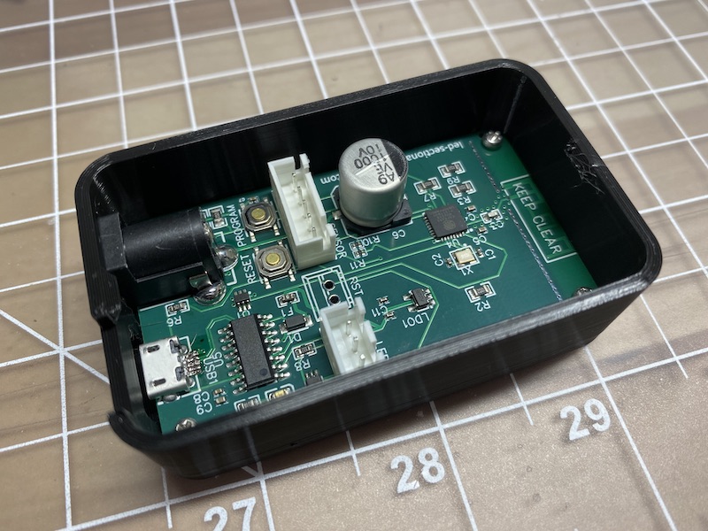
- A custom PCB that includes the following:
- An ESP8285 microcontroller and components and interfaces that replicate a WEMOS D1 Mini Lite development board.
- The following additional components included for connectivity and to comply with Adafruit’s Best Practices:
- 330 Ohm Resistor
- 1000 µF Capacitor
- 3-pin JST XH Connector to connect LEDs
- 5-pin JST XH Connector (if shipped with a light sensor) connected to the i2c bus for a TSL2561 light sensor
- 2x TS-1187A-B-A-B tacticle switches, one connected to the reset switch and one (“PROGRAM”) connected to GPIO12 (currently unused in the sketch)
- M74VHC1GT126DF1G logic level shifter to shift 3.3v logic to 5v logic for LEDs
- 2.1mm x 5.5mm DC Barrel Jack
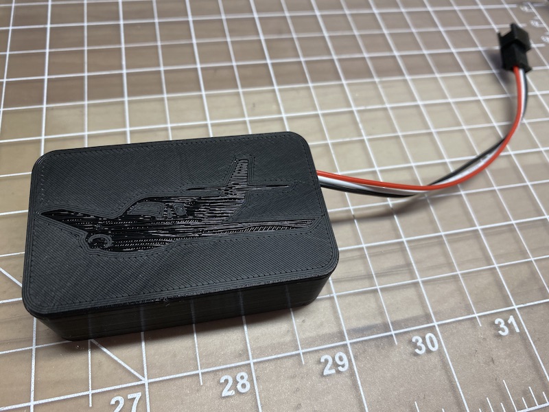
- Custom 3D printed case
- JST-XH to JST-SM cable for connecting LEDs.
Here’s are some pictures of what you get:


For the electronics, you’ll need to purchase the following items as well:
- WS2811 LED Strands (choose the 5V version)
- 5V Power Supply
You’ll also need to purchase sectionals, backing, glue, etc. to create and mount the map itself. The details about how I did that are documented here.
Using the Kit
The easiest way to set up your kit is using the LED Sectional Configuration Tool. This browser-based tool allows you to flash firmware, configure WiFi, and set up your airport list - all without installing any software.
For more details, see the full software instructions.
Limitations
There are a couple of limitations to note:
- This is still a DIY project. I’m trying to make it pretty polished, but it’ll be a little rough around the edges. The color of the case and the board may change.
- The kit only supports 2.4 GHz WiFi, and you should ensure that you have a solid signal wherever you plan to put the map.
- I’ve tested this to about 100 LEDs. It shouldn’t have much trouble handling any single sectional, but if you plan to use a much larger area let me know so I can test it ahead of time.
Open Source
Everything about the kit is open source. The firmware and web configuration tool source code is available on GitHub. If you’d like to make your own PCB, the Eagle files are in the pcb files folder, and if you have a 3D Printer the STL files for the enclosure are in the enclosure stl files folder.