LED Sectional
This project is adapted from a few other very similar ones:
There were small gaps in the how-to details for some of them so I figured it might be helpful to fully document how I did it. I also opted to use a microcontroller rather than a Raspberry Pi, so mine is different in that way too.
Pictures
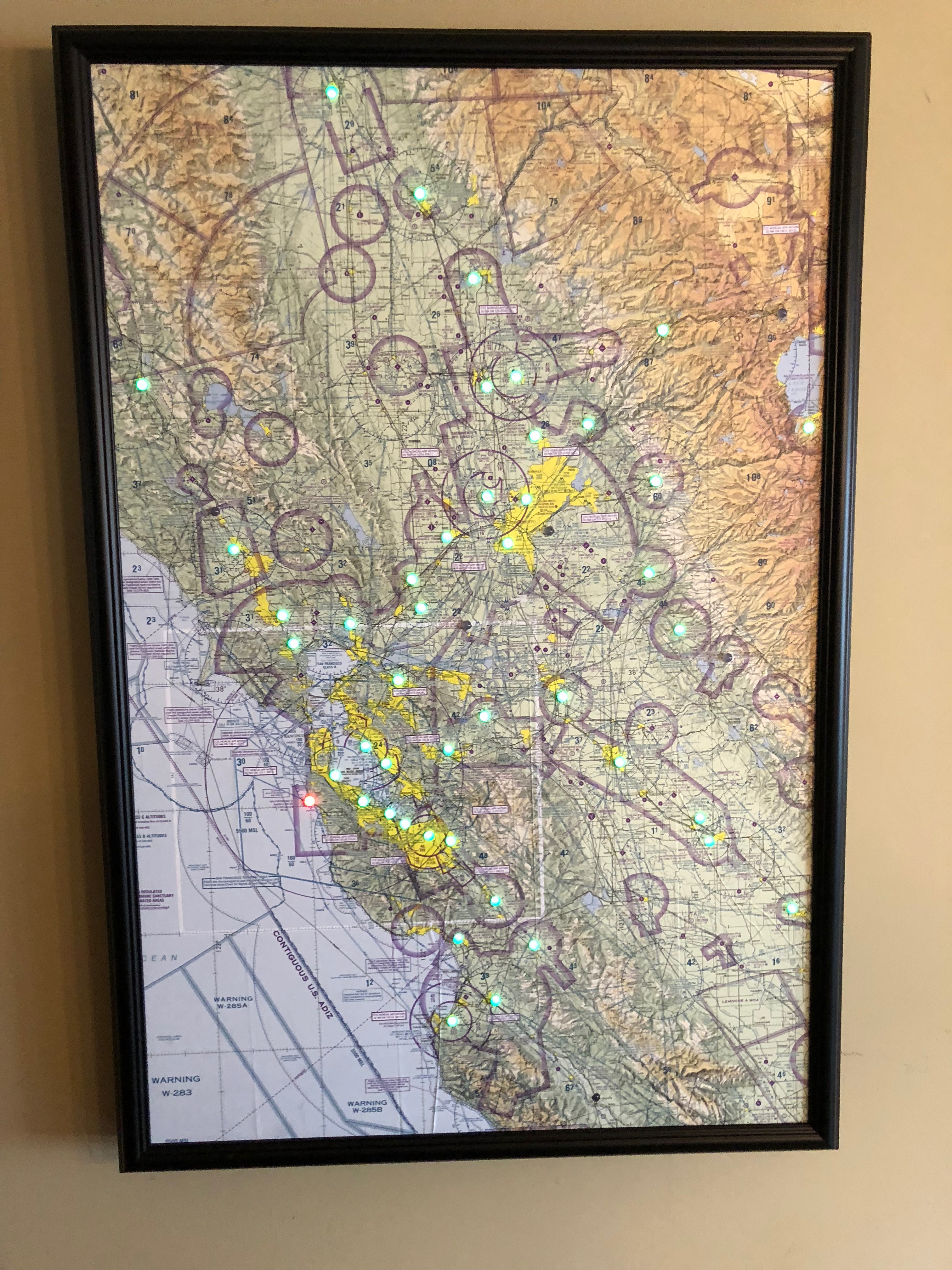
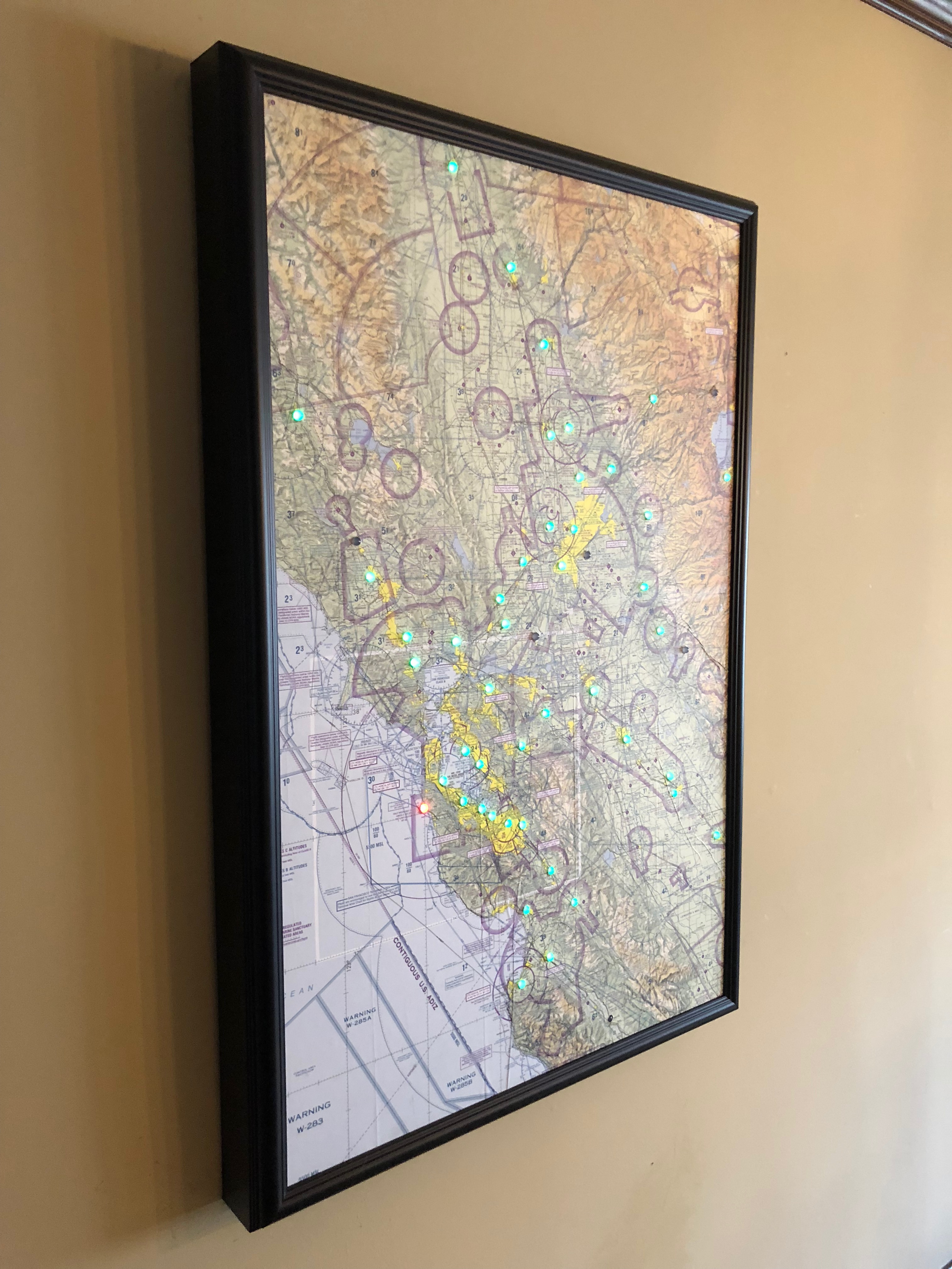
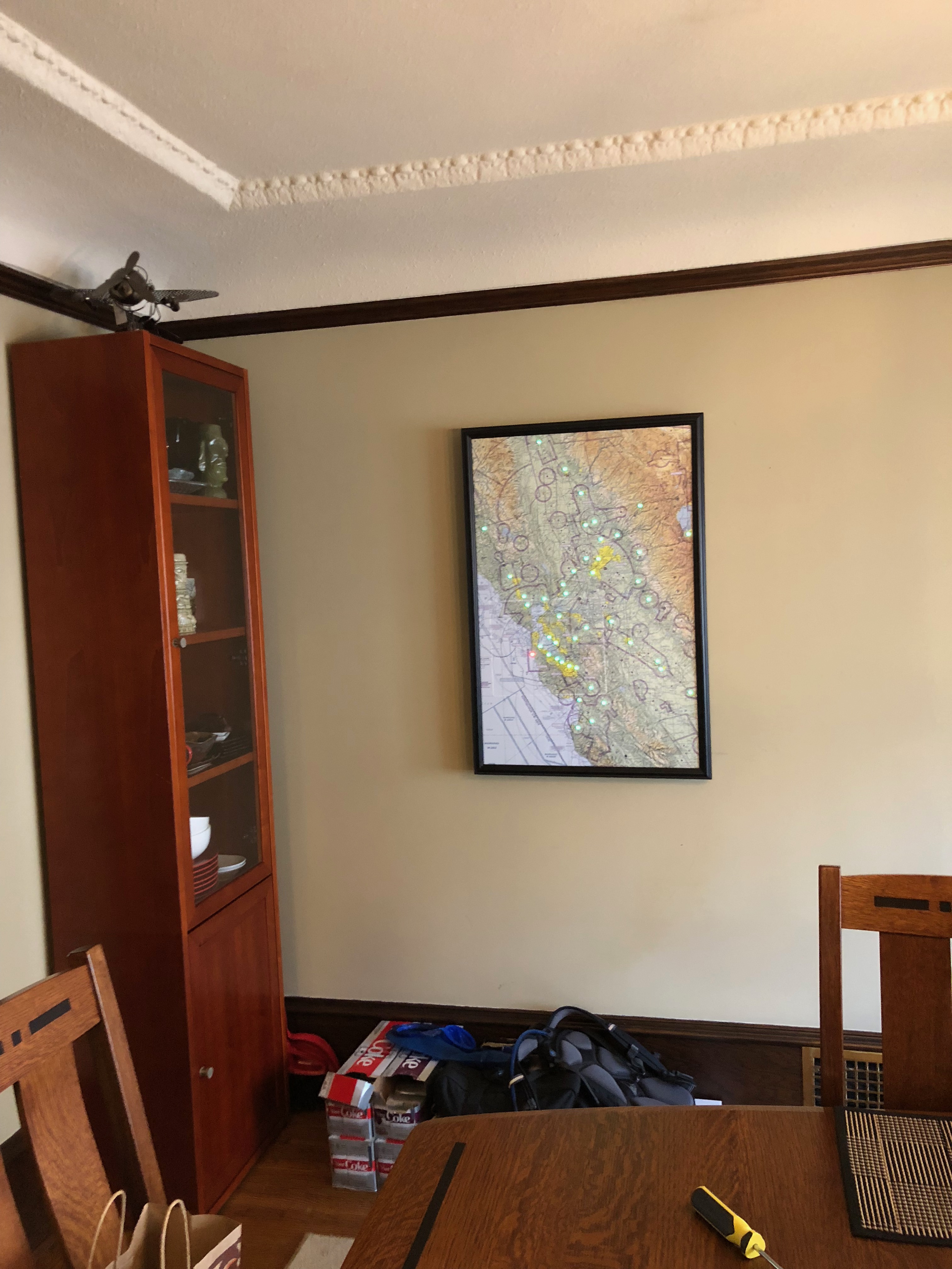
Here are a few pictures of the final product:
Things you’ll need
The materials themselves are pretty cheap–you should be able to get everything you need aside from the frame for less than $100. The frame cost will vary depending on how big you want to make the sectional. The tools may add some cost if you don’t already have what you need.
Electronics
LED Sectional Kit
I originally wrote this guide with instructions on how to buy all of the electronic components on Amazon, but now I have a kit available that contains all of the electronics except for the power adapter and the LED strands themslves. The kit is significantly cheaper than buying each of the components a la carte since most of the components come in large quantities.
Click here to find out more information about the kit.
The Amazon links from the original how-to are below in case you’d enjoy doing everything yourself.
Buying a la carte
I’ve linked to Amazon for most of the electronic items. You should be able to buy them for cheaper and in smaller quantites from Aliexpress or another similar store if you’re willing to wait for the shipment. (In the interest of full disclosure, the Amazon links do have my affiliate tags, but I’m not really trying to make any money here.)
- WEMOS D1 Mini Lite
- If you have time to wait for the shipment, support them and buy from the official store, but this version on Amazon also worked fine.
- The non-Lite version will work fine, and this code should be pretty adaptable to any Arduino-compatible board with WiFi.
- 3.3V to 5V Level Shifter
- WeiMeet 4 Channel Level Converter - These are what I originally used (and will document here), but they’re considered to be a bit slow. You may run into problems if you have a ton of LEDs.
- 74HCT245 are faster and are what I use in the kit.
- WS2811 LED Strand(s)
- 5V DC Power Supply - This is more power than you really need–you could get a smaller one if you’d prefer.
- DC Barrel Connectors
- Solid Core Hookup Wire - 22G worked well for me
- 3cm x 7cm PCB - This has a bunch of PCBs, I’m sure there’s a cheaper opton. Other sizes will work, but these fit nicely into a small project enclosure.
- Optional: 80mm x 50mm x 20mm Project Enclosure
- Optional: 3-pin JST-XH Connectors and JST-SM Connectors if you want a interface between the microcontroller and the LED strand(s)
- Optional: Velcro to affix the power supply and controller to the board
- Optional components recommended by NeoPixels that I didn’t add:
- 1000 µF, 6.3V or higher capacitor - put this between the 5v and Ground on the power adapter to mitigate spikes on power-on
- 220 Ohm resistor - put this on the data wire between the level shifter HV1 pin and the data wire on the connector to the LED strand to also mitigate power spikes
Map and Frame
You’ll also need either:
- Sectional(s) from the FAA - remember that they’re two sided so you may need two to get full coverage
- 3/8” Foamcore or Hard Tempered Board or MDF
- I used the board in my first map, but found foamcore to be much easier to work with on one I made for a friend.
- 3M Super 77 Spray Adhesive
- SP8 Picture Frame
- This is one of the only super-deep frames I’ve seen that are easily orderable online.
- Optional: PVA Adhesive if you have a seam between sectionals
OR
- Have a digital file of the sectional printed and mounted on foamcore at PictureFrames.com. If you do this, be sure to maintain the 300 ppi from the original file in order to keep the sectional to scale (assuming you want that at least).
- Use the SP8 Picture Frame for plenty of depth. The SP2 Picture Frame also works pretty well, but the wires may rub against the wall.
Tools
Here are the tools you’ll need. I’ve provided links to the ones I use, but any set of good tools will work.
If you used foamcore backing:
- Foamboard Hole Drill (You’ll use the smallest one in the set.)
If you used wood backing:
- Drill with a 7mm drill bit
If you went the a la carte route for the electronics, you’ll also need:
- Soldering iron and solder
- Wire stripper
- Optional: Crimper for JST connectors
Software
Web-Based Configuration (Recommended)
The easiest way to set up your LED Sectional is using the LED Sectional Configuration Tool. This browser-based tool allows you to:
- Flash firmware directly from your browser - no software installation required
- Configure WiFi by entering your network credentials
- Set up your airport list with a drag-and-drop interface
- Adjust settings like brightness, wind thresholds, and lightning effects
- Connect to Home Assistant for smart home control (optional)
Just connect your controller via USB, open the tool in Chrome, Edge, or Opera, and follow the on-screen instructions.
How It Works
The program uses standard definitions for VFR, MVFR, IFR, and LIFR, but also shows yellow if an airport is VFR with winds greater than 25 knots, and airports will flash white if there are thunderstorms in the area.
On power on, all LEDs will show orange initially. Once the controller is connected to the WiFi network, they’ll turn purple, and then they’ll show the airport colors once the data is downloaded and parsed. LEDs for airports that have not reported weather in the last 3 hours, or that don’t have a clear flight category will be turned off. Weather is updated every 5 minutes.
Manual Setup (Advanced)
If you prefer to program the board manually, the source code is available at https://github.com/WKHarmon/led-sectional. See the CONTRIBUTING.md file for development instructions.
Assembly
Soldering and Wiring
The following section is only necessary if you went the a la carte route.
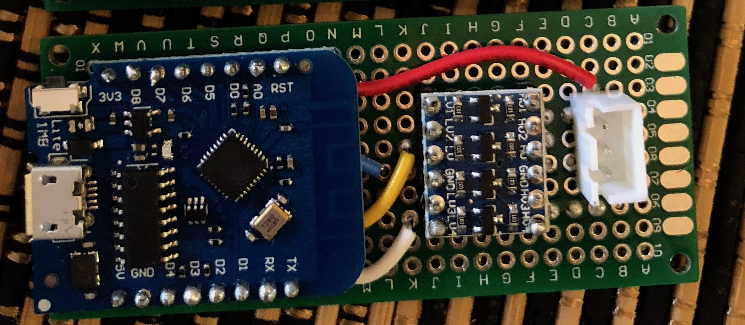
The Wemos D1 Mini Lite can accept 5V as input voltage, but the GPIO pins run at 3.3v. The WS2811 LED strand is expecting 5V on the data line, so it is necessary to convert the GPIO 3.3v to the WS2811 5V using a logic level shifter. (In some cases it may work without the shifter, but using one is the safer bet.) Below is a breadboard diagram for wiring it all up:
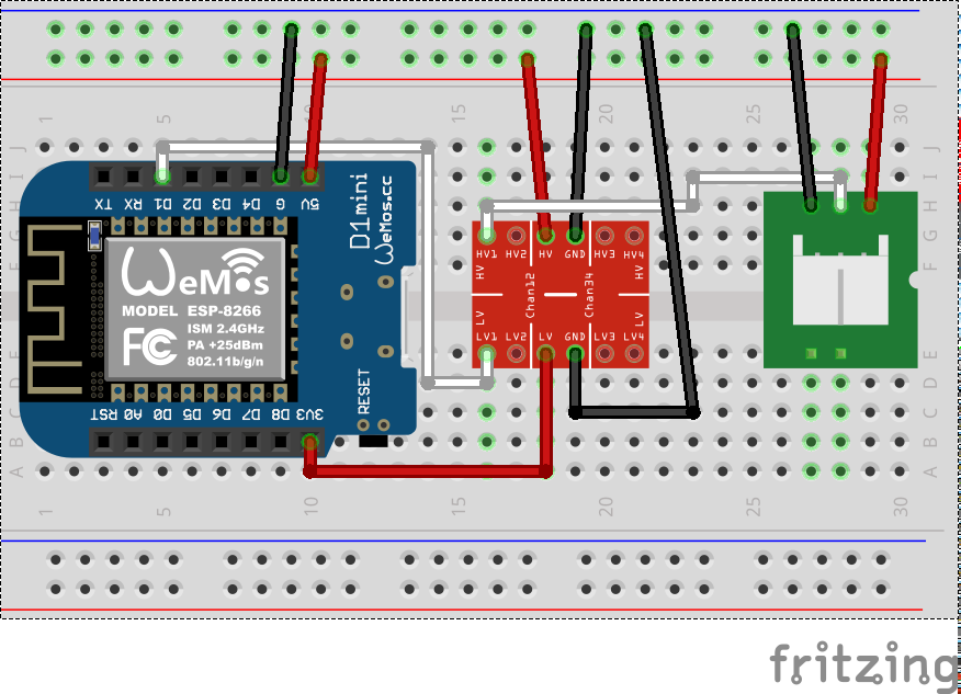
I’ve diagramed on a breadboard for simplicity, but I used a 3cm x 7cm PCB. In the diagram, the (optional) JST-XH connector on the right goes to the WS2811 LED strand. If you don’t want to bother with the connector, you can just solder the wires from the LED strand to the PCB.
If you have a smaller number of LEDs on your map, it may be possible to power the LED strand from the Micro USB port on the Wemos D1 Mini rather than connecting an external power supply. No wiring changes are necessary, but be sure to not connect an external power supply when the Micro USB port is connected. Also be aware that the Wemos D1 Mini has a 0.5A fuse on the 5V line so it would need to be a really small number of LEDs.
The data flow on the WS2811 strand is directional. In the LED pixel itself, the PCB will be marked with an arrow on one side. That arrow indicates the input side of the pixel. Connect the microcontroller to the side of the strand such that the wires from the controller are connected to the input side of the pixel (with the arrow), matching the 5V, Data, and Ground lines on the strand to those on the controller.
The WS2811 LED strand has pigtails for injecting power on the ends of the strand as well. Solder a DC barrel connector for power to the pigtails nearest the microcontroller. The microcontroller will receive power from its conenction to the LED strand.
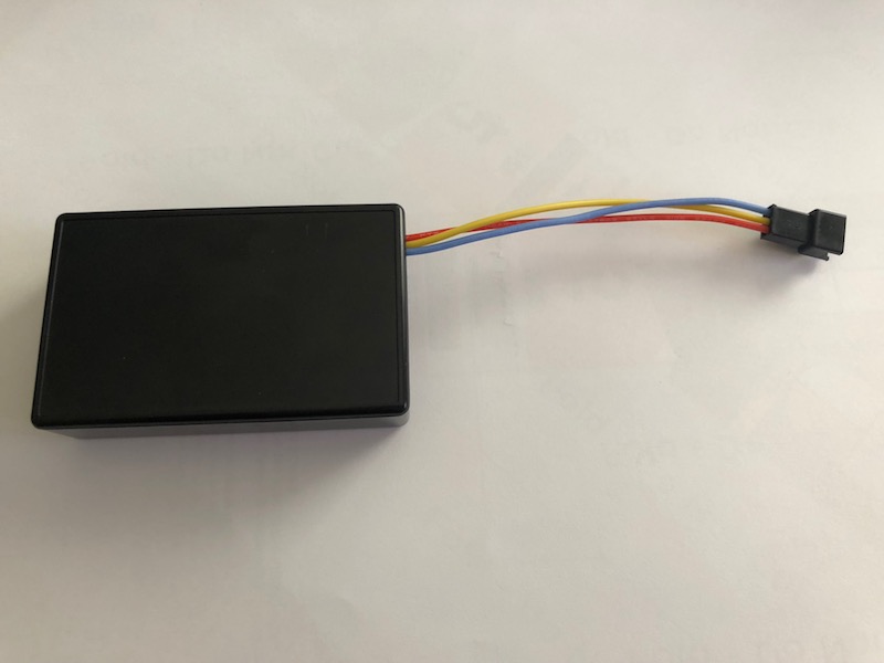
Once I had it all connected up, I created a small pigtail with a JST-XH connector on one side and a JST-SM connector on the other side (which matches the connectors that came with the LED strand) to make it easy to attach and detach the LED strand, then I put it in an enclosure box.
Mounting the sectionals
This section is only necessary if you bought actual sectionals and didn’t take the shortcut and have a sectional printed and pre-mounted.
When I bought the Hard Tempered Board noted above, I had Home Depot cut it to the desired size. The combined halves of the San Francisco sectional were just over 36” high, and the board itself was 24” wide, so I just decided to use that width.
I cut off the bottom white space of the northern sectional, then I taped the sectionals at the seam using scotch tape, and measured which 24” of the sectional width I actually wanted. I then put the board on top of the sectional and used an Exacto knife to cut off the excess parts of the sectional, but leaving about 1” on each side of the sectional just in case I didn’t get it perfectly centered when glueing.
Next, I sprayed the shiny side of the board with the 3M Spray Adhesive, waited about a minute per the directions, and then laid the sectional flat on the board so it would adhere. I used a ruler to flatten out any spots that were not flat.
Once the glue was dried, I cut off the excess parts of the sectional using an exacto knife, and then glued the flap created by the seam between the two sectionals using PVA Adhesive.
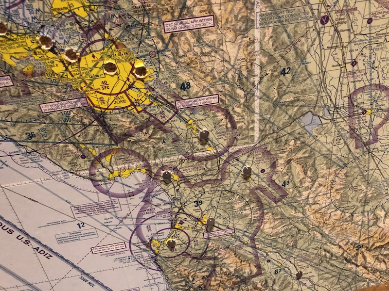
Drilling
Important: Don’t use ForeFlight to determine where METARs are available. ForeFlight aggregates several sources of weather data together, and contains several airports that are not available via the aviationweather.gov API. I suggest using the METAR map at aviationweather.gov to determine where to drill.
The Foamboard Holl Drill makes super clean cuts and is the perfect size for the LEDs, so I highly recommend grabbing that set if you used foamcore backing and drilling using them.
On my first board I used wood backing, which was quite a bit more challenging. I used a 7mm drill bit to drill through the sectional and the backing board together. This resulted in some holes that weren’t super clean.
I specifically wanted my LEDs to stick out, but if you don’t then adjusting the drill bit size and using a countersink bit would allow you to align them with the front of the board.
After I drilled, I then took a file and an exacto knife to clean up the edges to make it look significantly better.
Glueing LEDs
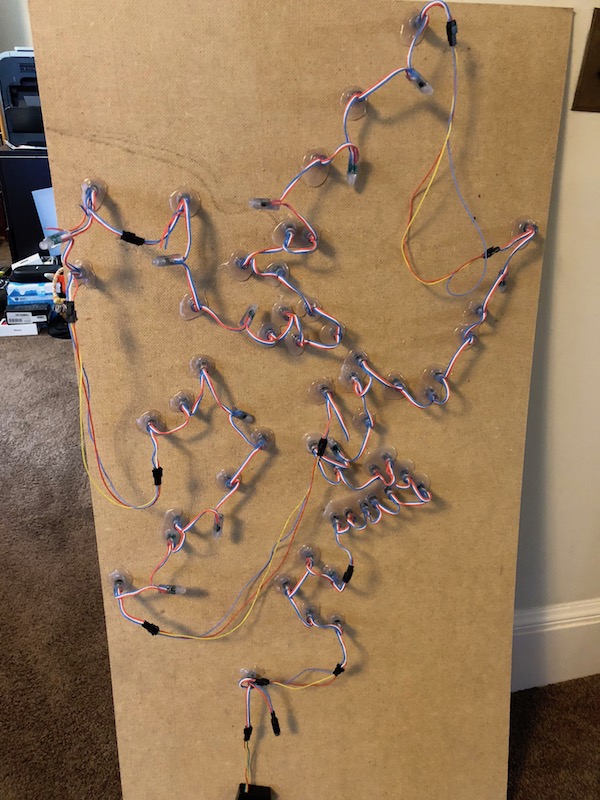
Once all of the holes were drilled, I rough fit the LEDs throught he holes in the back to try to find the optimal routing. IT’s not important what order they’re in yet–I’m just trying to waste the fewest LEDs. Once I figured it out, I started gluing a few at a time using the hot glue gun.
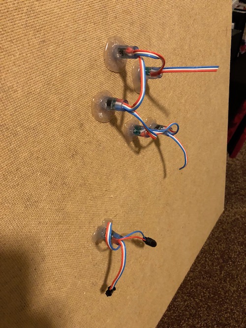
In the picture you can see that I cut the strand because the next LED in the strand was too far from the previous one, but eventually I realized that LEDs are cheap, so it is much easier to just leave the LEDs on the strand and not use them than to cut the strand and splice in a jumper. The final product looked like this:
Final Details
Because I don’t have good tools or really any skills with woodworking, I purchased a frame from http://www.pictureframes.com. Their SP8 frame has 2 1/4” of depth, which is plenty to contain the electronics. For my 24”x36 1/2” project, it cost me about $120 shipped for the frame, and it came fully assembled with mounting hardware (but no glass), which I thought was a pretty good details.
I mounted the map on a place on my wall previously had a wall sconce light, so I was able to re-use the existing power rather than running new power or running a cable.
Enjoy!